4.3. Managing Virtual Networks
In the compute cluster, you can create and manage two types of virtual networks:
- Private
- VXLAN-based overlay virtual networks that can be used for intercommunication between VMs. Each private network is isolated from other private networks as well as public networks.
- Public
Virtual networks that use IP address ranges of public physical networks. Such networks can be used to provide Internet access to VMs.
Each public virtual network can use IP addresses of only one physical network.
In Acronis Cyber Infrastructure, virtual networking also includes virtual routers and floating public IP addresses.
The next subsections explain the virtual network architecture and describe how to add, edit, and delete virtual networks as well as manage virtual routers and floating IP addresses.
4.3.1. Virtual Network Architecture
Acronis Cyber Infrastructure supports distributed virtual switching on the basis of Open vSwitch. Open vSwitch runs on every compute node and forwards network traffic between virtual machines on the same node and between virtual machines and physical networks. Distributed virtual switching provides centralized management and monitoring of virtual network configuration across all nodes in a compute cluster.
4.3.1.1. Private Network Connectivity
VXLAN technology used for private virtual networks allows creating logical L2 networks in L3 networks by encapsulating (tunneling) Ethernet frames over UDP packets.
The physical representation of private network connectivity can be shown as follows:
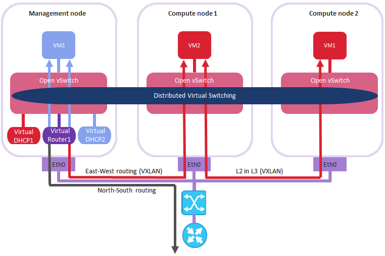
On the figure above:
- Three virtual machines are distributed across the compute cluster and connected to two private virtual networks via two virtual switches:
VM1andVM2belong to one private virtual network,VM3belongs to the other one. - For each virtual network, the DHCP server runs on the management node.
- The virtual router that runs on the management node connects the two private virtual networks and the public virtual network created on top of the physical one, thus enabling connectivity between the VMs from different private virtual networks.
- The compute nodes are connected to the physical switch via the
eth0network interfaces and reside in one L2 segment. - The
eth0network interfaces are connected to the physical network with theVM privateandVM publictraffic types. - The physical router provides access to public networks, such as the Internet.
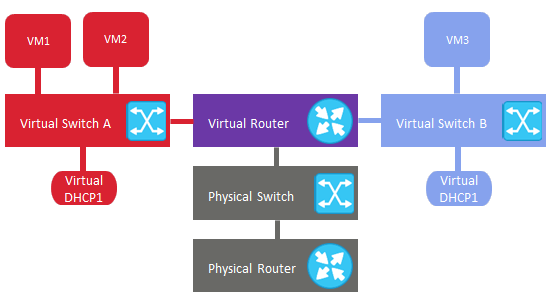
Logically the private networking scheme can be represented as follows:
4.3.1.2. Public Network Connectivity
Public virtual networks are connected to physical networks on Layer 2.
The physical representation of public network connectivity can be shown as follows:
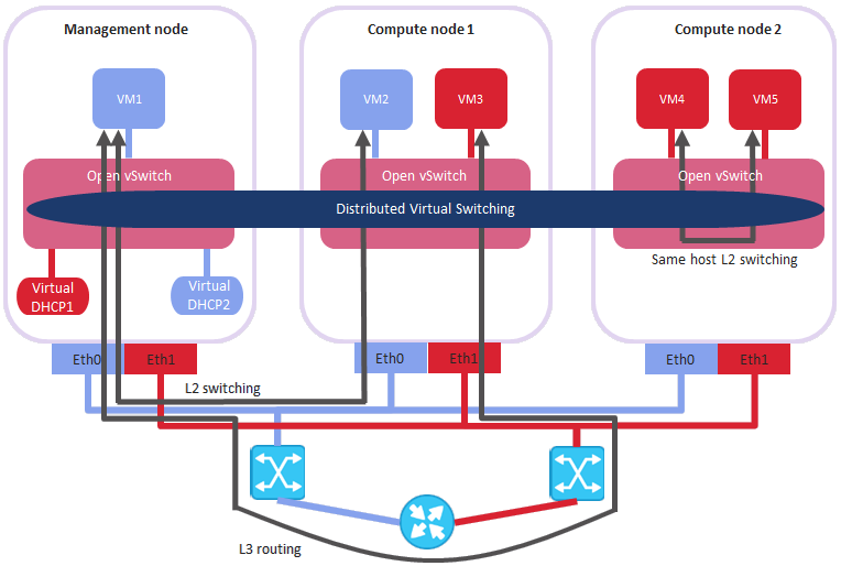
On the figure above:
- Five virtual machines are distributed across the compute cluster and connected to two public virtual networks via two physical switches:
VM1andVM2belong to one public virtual network, whileVM3,VM4, andVM5belong to the other one. - For each virtual network, the DHCP server runs on the management node.
- The compute nodes are connected to one physical switch via the
eth0network interfaces and to the other physical switch viaeth1and reside in two separate L2 segments. - The
eth0andeth1network interfaces are connected to the physical networks with theVM publictraffic type. - The physical router interconnects two public virtual networks created on top of the physical ones and provides access to public networks, such as the Internet.
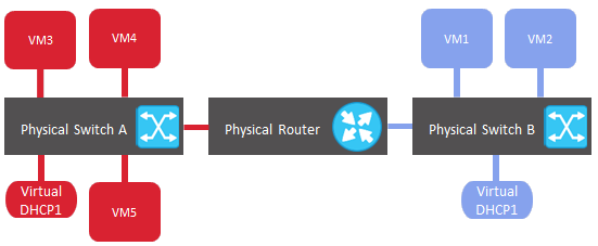
Logically the public networking scheme can be represented as follows:
4.3.2. Creating, Editing, and Deleting Virtual Networks
To add a new virtual network, do the following:
On the COMPUTE > Networks > NETWORKS tab, click Create virtual network.
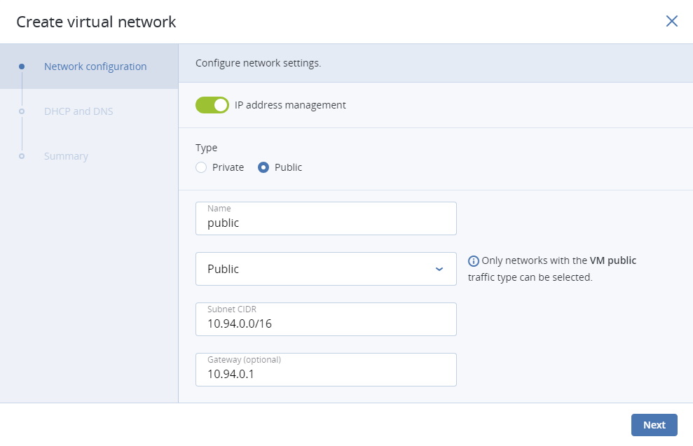
In the Network configuration section, configure the network parameters:
Enable or disable IP address management.
With IP address management enabled, Acronis Cyber Infrastructure will handle virtual machine IP addresses and provide the following features:
- Allocation pools. You can specify ranges of IP addresses that will be automatically assigned to VMs.
- Built-in DHCP server. Assigns IP addresses to virtual machines. With the DHCP server enabled, VM network interfaces will automatically be assigned IP addresses: either from allocation pools or, if there are no pools, from network’s entire IP range. With the DHCP server disabled, VM network interfaces will still get IP addresses, but you will have to manually assign them inside VMs.
- Custom DNS servers. You can specify DNS servers that will be used by VMs. These servers will be delivered to virtual machines via the built-in DHCP server.
With IP address management disabled:
- VMs connected to a network will be able to obtain IP addresses from DHCP servers in that network.
- Spoofing protection will be disabled for all VM network ports. Each VM network interface will accept all traffic, even frames addressed to other network interfaces.
In any case, you will be able to manually assign static IP addresses from inside VMs.
Choose network type.
Provide network details depending on type:
- For a private network, specify a name. If IP address management is enabled, specify network’s IPv4 address range in Subnet CIDR. Optionally specify a gateway. If you leave the Gateway field blank, the gateway will be omitted from network settings.
- For a public network, specify a name and choose a physical network with the VM public traffic type (that is not already used by a public network). If IP address management is enabled, optionally specify a gateway. If you leave the Gateway field blank, the gateway will be omitted from network settings. The Subnet CIDR field will be filled in automatically. Optionally, select the Share between all projects checkbox. With the disabled option, the public network will only be available in the admin project of the Default domain.
Click Next.
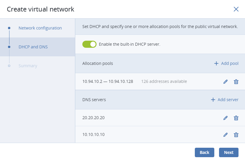
If you enabled IP address management on the previous step, you will move on to the DHCP and DNS section. In it, enable or disable the built-in DHCP server and specify one or more allocation pools and DNS servers. Click Next.
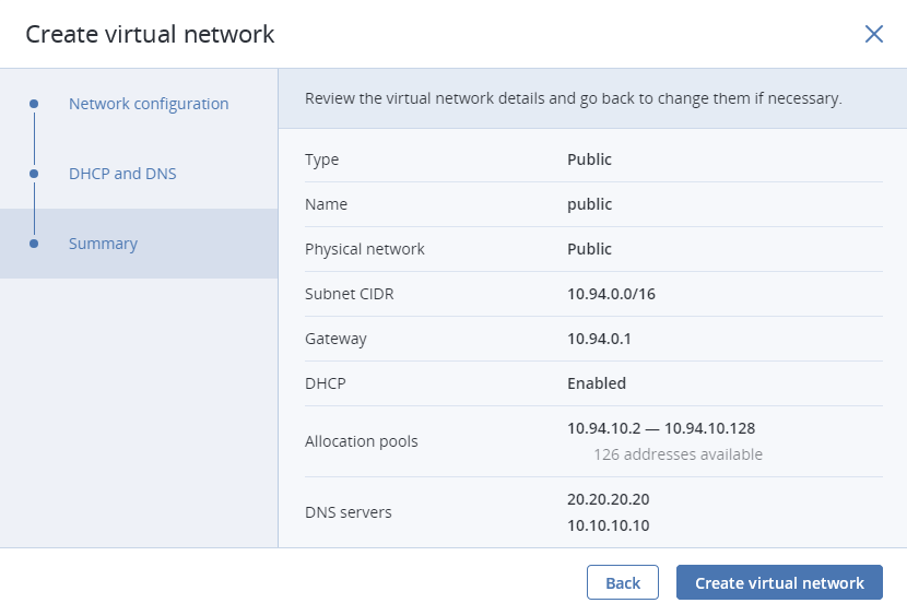
In the Summary section, review the configuration and click Add virtual network.
To view and edit parameters of a virtual network, click it on the NETWORKS tab. On the virtual network panel, you can change the virtual network name, gateway, DHCP settings, allocation pools, and DNS servers. To do this, click the pencil icon, enter a new value, and click the check mark icon to confirm.
To delete a virtual network, click the ellipsis icon next to it and Delete. To remove multiple virtual networks at once, select them and click Delete. Before deleting a virtual network, make sure no VMs are connected to it.
4.3.3. Managing Virtual Routers
Virtual routers provide L3 services such as routing and Source Network Address Translation (SNAT) between private and public networks or different private networks:
- a virtual router between private and public networks provides access to public networks, such as the Internet, for VMs connected to this private network;
- a virtual router between different private networks provides network communication for VMs connected to these private networks.
A virtual router has two types of ports:
- an external gateway that is connected to a public network,
- an internal port that is connected to a private network.
Note
A router can only connect networks with enabled IP management.
To create a virtual router, do the following:
On the COMPUTE > Networks > NETWORKS tab, make sure the virtual networks that are to be connected to a router have a gateway specified.
Navigate to the ROUTERS tab and click Add router.
In the Add router window:
- Specify a router name.
- From the Network drop-down menu, select a public network through which external access will be provided via an external gateway. The new external gateway will pick an unused IP address from the selected public network.
- In the Add internal interfaces section, select one or more private networks to connect to a router via internal interfaces. The new internal interfaces will attempt to use the gateway IP address of the selected private networks by default.
- Optionally, select or deselect the SNAT checkbox to enable or disable SNAT, respectively, on the external gateway of the router. With SNAT enabled, the router replaces VM private IP addresses with the public IP address of its external gateway.
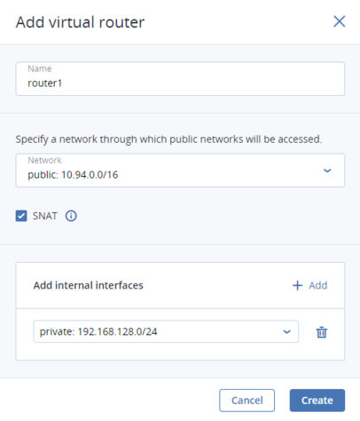
Click Create.
To edit a router name, click the ellipsis icon next to it and Rename.
To remove a virtual router, click the ellipsis icon next to it and Delete. To remove multiple virtual networks at once, select them and click Delete. Before deleting a virtual router, make sure no floating IP addresses are associated with any network it is connected to.
4.3.3.1. Managing Router Interfaces
You can add an external router interface as follows:
Note
To change an external gateway, remove the existing one first.
On Routers screen, click the router name to open the list of its interfaces.
Click Add.
In the Add interface window, do the following:
- Choose External gateway.
- From the Network drop-down menu, select a public network to connect to the router. The new interface will pick an unused IP address from the selected public network. You can also provide a specific IP address from the selected public network to assign to the interface in the IP address field.
- Optionally, select or deselect the SNAT checkbox to enable or disable SNAT, respectively, on the external gateway of the router. With SNAT enabled, the router replaces VM private IP addresses with the public IP address of its external gateway.
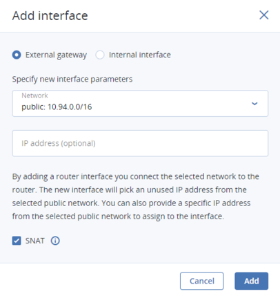
Click Add.
To edit the external gateway parameters, click the ellipsis icon next to it and Edit. In the Edit interface window, you can change the external gateway IP address and enable or disable SNAT on it. To save your changes, click Save.
You can add an internal router interface as follows:
On Routers screen, click the router name to open the list of its interfaces.
Click Add.
In the Add interface window, select a network to connect to the router from the Network drop-down menu. The new interface will attempt to use the gateway IP address of the selected private network by default. If it is in use, specify an unused IP address from the selected private network to assign to the interface in the IP address field.
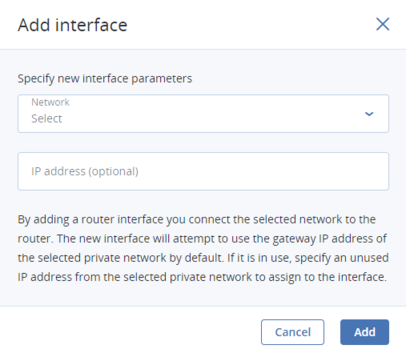
Click Add.
To remove a router interface, click the ellipsis icon next to it and Delete. To remove multiple interfaces at once, select them and click Delete.
4.3.3.2. Managing Static Routes
You can also configure static routes of a router by manually adding entries into its routing table. This can be useful, for example, if you do not need a mutual connection between two private networks and want only one private network to be accessible from the other.
Consider the following example:
- the virtual machine
vm1is connected to the private networkprivate1(192.168.128.0/24) via the network interface with IP address192.168.128.10, - the virtual machine
vm2is connected to the private networkprivate2(192.168.30.0/24) via the network interface with IP address192.168.30.10, - the router
router1connects the networkprivate1to the public network via the external gateway with the IP address10.94.129.73, - the router
router2connects the networkprivate2to the public network via the external gateway with the IP address10.94.129.74.
To be able to access vm2 from vm1, you need to add a static route for router1, specifying the CIDR of private2, that is 192.168.30.0/24, as the destination subnet and the external gateway IP address of router2, that is 10.94.129.74, as the next hop IP address. In this case, when an IP packet for 192.168.30.10 reaches router1, it will be forwarded to router2 and then to vm2.
To create a static route for a router, do the following:
On the STATIC ROUTES tab of a virtual router, click Add static route.
In the Add static route window, specify the destination subnet range and mask in CIDR notation and the next hop’s IP address. The next hop’s IP address must belong to one of the networks that the router is connected to.
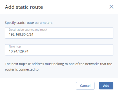
Click Add.
To edit a static route, click the ellipsis icon next to it and Edit. In the Edit static route window, change the desired parameters and click Save.
To remove a static route, click the ellipsis icon next to it and Delete. To remove multiple routes at once, select them and click Delete.
4.3.4. Managing Floating IP Addresses
A virtual machine connected to a virtual private network can be accessed from public networks, such as the Internet, by means of a floating IP address. Such an address is picked from a public network and mapped to VM’s private IP address. The floating and private IP addresses are used at the same time on the VM’s network interface. The private IP address is used to communicate with other VMs on the private network. The floating IP address is used to access the VM from public networks. The VM guest operating system is unaware of the assigned floating IP address.
Note the following prerequisites:
- A VM must have a fixed private IP address.
- A virtual router must connect the public network from which a floating IP will be picked with VM’s private network.
You can create a floating IP address and assign it to a VM as follows:
On the COMPUTE > Networks > FLOATING IPS tab, click Add floating IP.
In the Add floating IP address, select a public network from which a floating IP will be picked and a VM network interface with a fixed private IP address.
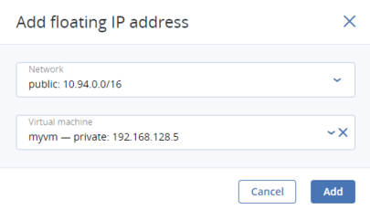
Click Add.
A floating IP address can be re-assigned to another virtual machine. Do the following:
- Click the ellipsis icon next to the floating IP address and then click Unassign.
- Once the VM name disappears in the Assigned to column, click the ellipsis icon again and choose Assign.
- In the Assign floating IP address window, select a VM network interface with a fixed private IP address.
- Click Assign.
To remove a floating IP address, unassign it from a VM as described above, then click the ellipsis icon again and choose Delete.