5.8. Managing the compute network
In Acronis Cyber Infrastructure, compute networking includes compute networks, virtual routers, floating public IP addresses, and network load balancers.
The next subsections explain the compute network types and architecture, describe how to add, edit, and delete compute networks, as well as manage virtual routers, floating IP addresses, and load balancers.
5.8.1. Compute network types
In the compute cluster, you can create and manage two types of networks: virtual and physical.
5.8.1.1. Virtual networks
Virtual networks are VXLAN-based overlay networks that can be used for intercommunication between virtual machines (VMs). Each virtual network is isolated from other virtual networks, as well as physical networks.
5.8.1.2. Physical networks
Physical networks use IP address ranges of public infrastructure networks. Such networks can be used to provide Internet access to VMs.
If you plan to use a large number of VLAN-based networks for virtual machines, you can benefit from the automated procedure of VLAN-based network creation. When you create a VLAN-based network in the compute cluster, the system automatically creates an associated infrastructure network and configures VLAN network interfaces on all of the compute nodes via the distributed virtual switch.
To use the automated procedure, consider the following cases:
- If your trunk network interfaces have a virtual switch (their names have the format
br-<interface>), you can proceed to creating VLAN-based networks in the compute cluster. - If your trunk network interfaces have neither VLANs nor virtual switch configured, assign the VM public traffic type to the infrastructure network connected to those trunk interfaces. The virtual switch will be configured automatically on the trunk network interfaces after creating a VLAN-based network.
- If you have existing VLANs but no virtual switch configured on the trunk network interfaces, convert the trunk interface configuration to the virtual switch one, first. To do this, use the
vinfra cluster network conversioncommands (refer to vinfra cluster network conversion precheck). During the conversion you may experience connection timeouts. When the conversion is complete, you will be able to create more VLANs on the trunk network interfaces by using the simplified procedure.
If your network configuration includes only a few VLAN-based networks, you can create VLAN network interfaces separately on each compute node, as described in Creating VLAN interfaces.
Important
For VLAN-based networks, the corresponding VLAN IDs must be configured on the physical switches connected to the compute nodes.
5.8.2. Compute network architecture
Acronis Cyber Infrastructure supports distributed virtual switching on the basis of Open vSwitch. The latter runs on every compute node and forwards network traffic between virtual machines on the same node, and between virtual machines and infrastructure networks. Distributed virtual switching provides centralized management and monitoring of virtual network configuration across all nodes in the compute cluster.
Distributed virtual routing used for virtual network connectivity enables placing virtual routers on compute nodes and routing VM traffic directly from hosting nodes. In the DNAT scenario, a floating IP is assigned directly to the VM’s network interface. If SNAT is used, then traffic is routed via management nodes.
5.8.2.1. Virtual network connectivity
VXLAN technology used for virtual networks allows creating logical L2 networks in L3 networks by encapsulating (tunneling) Ethernet frames over UDP packets.
The physical representation of virtual network connectivity can be shown as follows:
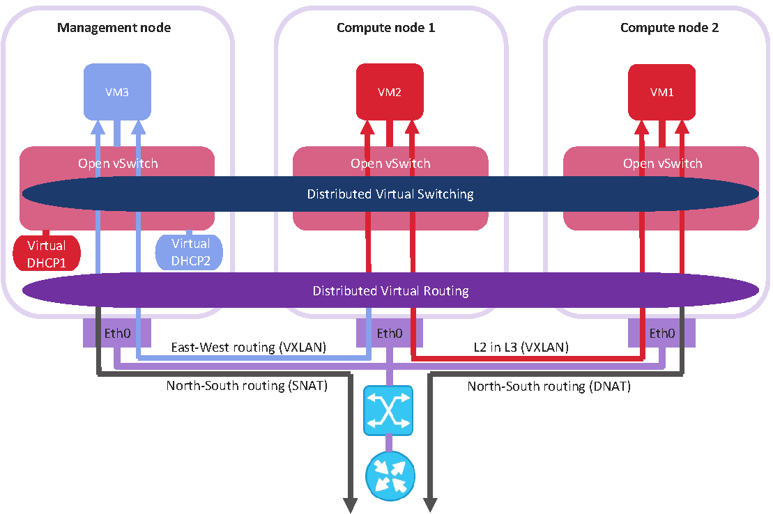
On the figure above:
- Three virtual machines are distributed across the compute cluster and connected to two virtual networks via two virtual switches:
VM1andVM2belong to one virtual network,VM3belongs to the other one. - For each compute network, the DHCP server runs on the management node.
- The distributed virtual router connects the virtual networks and the untagged physical network created on top of the infrastructure one.
- The compute nodes are connected to the physical switch via the
eth0network interfaces and reside in one L2 segment. - The
eth0network interfaces are connected to the infrastructure network with theVM privateandVM publictraffic types. - The physical router provides access to public networks, such as the Internet.
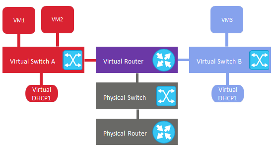
Logically, the virtual networking scheme can be represented as follows:
5.8.2.2. Physical network connectivity
Physical networks are connected to infrastructure networks on Layer 2.
The physical representation of physical network connectivity can be shown as follows:
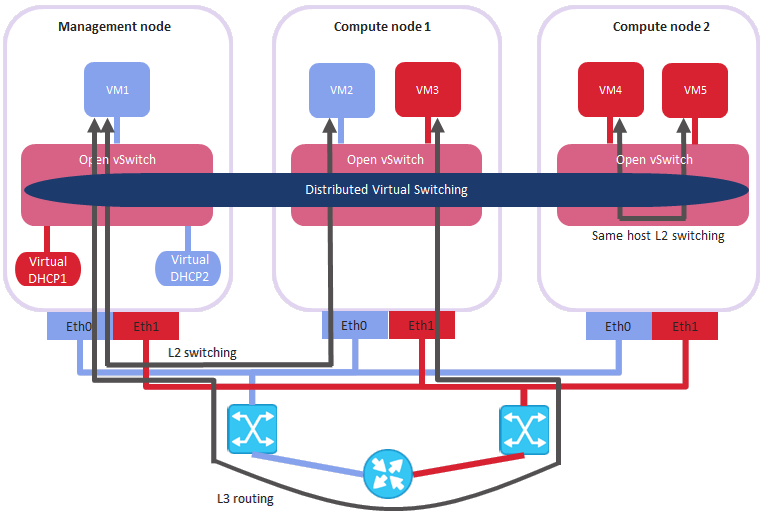
On the figure above:
- Five virtual machines are distributed across the compute cluster and connected to two untagged physical networks via two physical switches:
VM1andVM2belong to one physical network, whileVM3,VM4, andVM5belong to the other one. - For each compute network, the DHCP server runs on the management node.
- The compute nodes are connected to one physical switch via the
eth0network interfaces, and to the other physical switch viaeth1, and reside in two separate L2 segments. - The
eth0andeth1network interfaces are connected to the infrastructure networks with theVM publictraffic type. - The physical router interconnects two physical networks created on top of the infrastructure ones and provides access to public networks, such as the Internet.
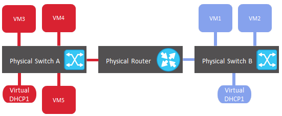
Logically, the physical networking scheme can be represented as follows:
5.8.3. Creating, editing, and deleting compute networks
To add a new compute network, do the following:
On the Compute > Network > Networks tab, click Create network.
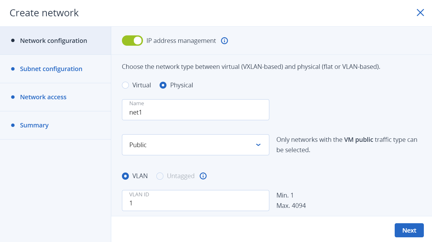
On the Network configuration step, do the following:
Enable or disable IP address management:
- With IP address management enabled, VMs connected to the network will automatically be assigned IP addresses from allocation pools by the built-in DHCP server and use custom DNS servers. Additionally, spoofing protection will be enabled for all VM network ports by default. Each VM network interface will be able to accept and send IP packets only if it has IP and MAC addresses assigned. You can disable spoofing protection manually for a VM interface, if required.
- With IP address management disabled, VMs connected to the network will obtain IP addresses from the DHCP servers in that network, if any. Also, spoofing protection will be disabled for all VM network ports, and you cannot enable it manually. This means that each VM network interface, with or without assigned IP and MAC addresses, will be able to accept and send IP packets.
In any case, you will be able to manually assign static IP addresses from inside the VMs.
Select the network type: virtual (VXLAN-based) or physical (flat or VLAN-based).
Provide the network details, depending on the type:
For a virtual network, specify a name.
For a physical network, specify a name and select an infrastructure network with the VM public traffic type. Then, select VLAN and specify a VLAN ID to create a VLAN-based network, or select Untagged to create a flat physical network.
Note
You can create only one untagged network over an infrastructure network.
Click Next.
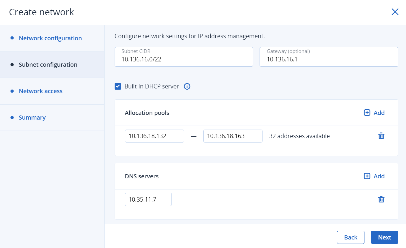
If you enabled IP address management, you will move on to the Subnet configuration step, where you can configure the network settings for IP address management:
- Specify the network’s IPv4 address range and, optionally, specify a gateway. If you leave the Gateway field blank, the gateway will be omitted from network settings.
Enable or disable the built-in DHCP server:
- With the DHCP server enabled, VM network interfaces will automatically be assigned IP addresses: either from allocation pools or, if there are no pools, from the network’s entire IP range.
- With the DHCP server disabled, VM network interfaces will still get IP addresses, but you will have to manually assign them inside VMs.
The virtual DHCP service will work only within the current network and will not be exposed to other networks.
Specify one or more allocation pools (ranges of IP addresses that will be automatically assigned to VMs).
Specify DNS servers that will be used by virtual machines. These servers can be delivered to VMs via the built-in DHCP server or by using the cloud-init network configuration (if cloud-init is installed in the VM).
Click Next.
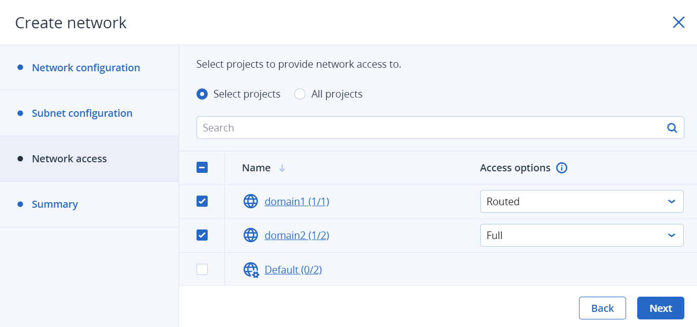
If you selected to create a physical network, you will move on to the Network access step, where you can configure the network access:
Select projects to provide network access to:
- If you want the network to be accessed from all existing and new projects, select All projects.
- If you want the network to be accessed from all projects within a domain, select Select projects, and then select the check box next to the required domain.
- If you want the network to be accessed from a particular project within a domain, select Select projects, click the domain name, and then select the required project.
- If you do not want to share the network, skip this step by clicking Next.
Select the access type:
- By providing full access, you allow virtual machines in the selected projects to communicate with this network either directly or via virtual routers.
- By providing routed access, you allow virtual machines in the selected projects to communicate with this network only via virtual routers.
You can also provide direct access, which implies a direct connection of virtual machines within projects to a physical network. Direct access can be granted only via the
vinfratool by specifyingsharedin the--rbac-policiesoption (refer to vinfra service compute network create). You cannot configure this access type in the admin panel.Click Next.
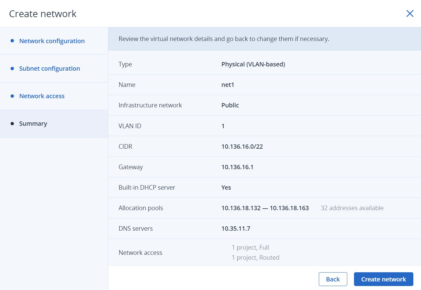
On the Summary step, review the configuration, and then click Add network.
When you create load balancers or Kubernetes clusters with highly available master nodes, the lb-mgmt-net virtual network appears in the compute cluster. This network is used by the system for load balancing. It is marked with the System tag and cannot be modified or deleted.
To view and edit parameters of a compute network, click it on the Networks tab. On the network right pane, you can edit the network name, IP management settings, and network access. To do this, click the pencil icon next to the required section, and then make your changes.
To delete a compute network, click the ellipsis icon next to it, and then click Delete. To remove multiple compute networks at once, select them, and then click Delete. Before deleting a compute network, make sure no VMs are connected to it.
5.8.4. Managing virtual routers
Virtual routers provide L3 services such as routing and Source Network Address Translation (SNAT) between virtual and physical networks, or different virtual networks:
- A virtual router between virtual and physical networks provides access to public networks, such as the Internet, for VMs connected to this virtual network.
- A virtual router between different virtual networks provides network communication for VMs connected to these virtual networks.
A virtual router has two types of ports:
- An external gateway that is connected to a physical network.
- An internal port that is connected to a virtual network.
Note
A router can only connect networks that have IP management enabled.
To create a virtual router, do the following:
On the Compute > Network > Networks tab, make sure the compute networks that are to be connected to a router have a gateway specified.
Navigate to the Routers tab, and then click Add router.
In the Add router window:
- Specify a router name.
- From the Network drop-down menu, select a physical network through which external access will be provided via an external gateway. The new external gateway will pick an unused IP address from the selected physical network.
- In the Add internal interfaces section, select one or more virtual networks to connect to a router via internal interfaces. The new internal interfaces will attempt to use the gateway IP address of the selected virtual networks by default.
- (Optional) Select or deselect the SNAT check box to enable or disable SNAT on the external gateway of the router. With SNAT enabled, the router replaces VM private IP addresses with the public IP address of its external gateway.
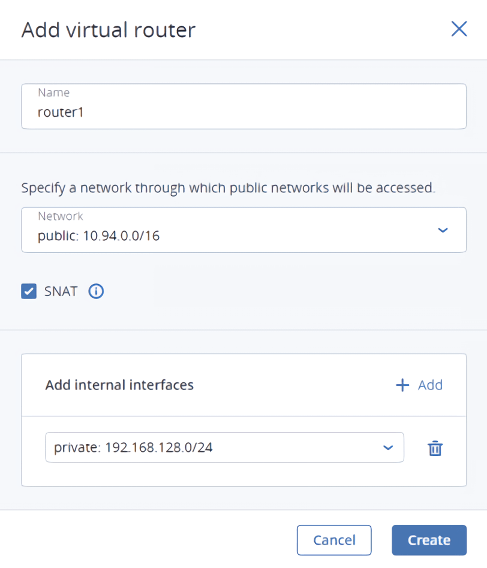
Click Create.
To edit a router name, click the ellipsis icon next to it, and then click Rename.
To remove a virtual router, click the ellipsis icon next to it, and then click Delete. To remove multiple virtual routers at once, select them, and then click Delete. Before deleting a virtual router, make sure no floating IP addresses are associated with any network it is connected to.
5.8.4.1. Managing router interfaces
To add an external router interface, do the following:
If you already have an external gateway, remove the existing one first.
On the Routers screen, click the router name to open the list of its interfaces.
Click Add on the toolbar, or click Add interface if there are no interfaces to show.
In the Add interface window, do the following:
- Select External gateway.
- From the Network drop-down menu, select a physical network to connect to the router. The new interface will pick an unused IP address from the selected physical network. You can also provide a specific IP address from the selected physical network to assign to the interface in the IP address field.
- (Optional) Select or deselect the SNAT check box to enable or disable SNAT on the external gateway of the router. With SNAT enabled, the router replaces VM private IP addresses with the public IP address of its external gateway.
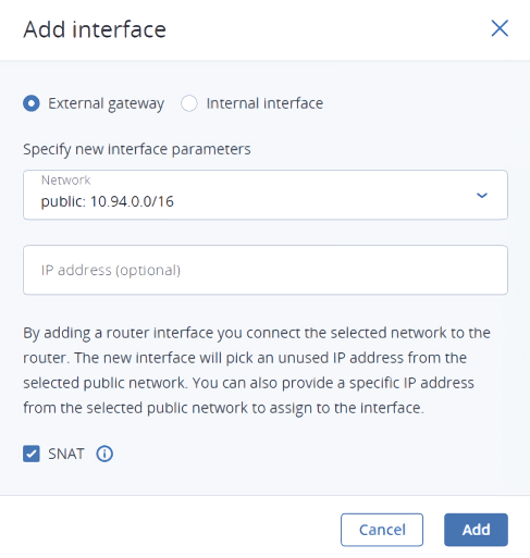
Click Add.
To edit the external gateway parameters, click the ellipsis icon next to it, and then Edit. In the Edit interface window, you can change the external gateway IP address and enable or disable SNAT on it. To save your changes, click Save.
To add an internal router interface, do the following:
On the Routers screen, click the router name to open the list of its interfaces.
Click Add.
In the Add interface window, select a network to connect to the router from the Network drop-down menu. The new interface will attempt to use the gateway IP address of the selected virtual network by default. If it is in use, specify an unused IP address from the selected virtual network to assign to the interface in the IP address field.
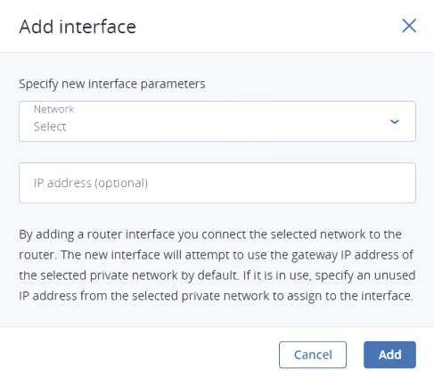
Click Add.
To remove a router interface, click the ellipsis icon next to it, and then click Delete. To remove multiple interfaces at once, select them, and then click Delete.
5.8.4.2. Managing static routes
You can also configure static routes of a router by manually adding entries into its routing table. This can be useful, for example, if you do not need a mutual connection between two virtual networks and want only one virtual network to be accessible from the other.
Consider the following example:
- The virtual machine
VM1is connected to the virtual networkprivate1(192.168.128.0/24) via the network interface with IP address192.168.128.10. - The virtual machine
VM2is connected to the virtual networkprivate2(192.168.30.0/24) via the network interface with IP address192.168.30.10. - The router
router1connects the networkprivate1to the physical network via the external gateway with the IP address10.94.129.73. - The router
router2connects the networkprivate2to the physical network via the external gateway with the IP address10.94.129.74.
To be able to access VM2 from VM1, you need to add a static route for router1, specifying the CIDR of private2, that is 192.168.30.0/24, as the destination subnet and the external gateway IP address of router2, that is 10.94.129.74, as the next hop IP address. In this case, when an IP packet for 192.168.30.10 reaches router1, it will be forwarded to router2 and then to VM2.
To create a static route for a router, do the following:
On the Static routes tab of a virtual router, click Add static route.
In the Add static route window, specify the destination subnet range and mask in CIDR notation and the next hop’s IP address. The next hop’s IP address must belong to one of the networks that the router is connected to.
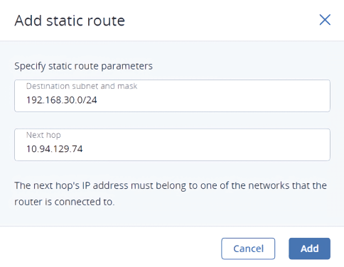
Click Add.
To edit a static route, click the ellipsis icon next to it, and then click Edit. In the Edit static route window, change the desired parameters, and then click Save.
To remove a static route, click the ellipsis icon next to it, and then click Delete. To remove multiple routes at once, select them, and then click Delete.
5.8.5. Managing floating IP addresses
A virtual machine connected to a virtual network can be accessed from public networks, such as the Internet, by means of a floating IP address. Such an address is picked from a physical network and mapped to the VM’s private IP address. The floating and private IP addresses are used at the same time on the VM’s network interface. The private IP address is used to communicate with other VMs on the virtual network. The floating IP address is used to access the VM from public networks. The VM guest operating system is unaware of the assigned floating IP address.
Note the following prerequisites:
- A VM must have a fixed private IP address.
- A virtual router must connect the physical network, from which a floating IP will be picked, with the VM’s virtual network.
To create a floating IP address and assign it to a VM, do the following:
On the Compute > Network > Floating IPs tab, click Add floating IP.
In the Add floating IP address, select a physical network, from which a floating IP will be picked, and a VM network interface with a fixed private IP address.
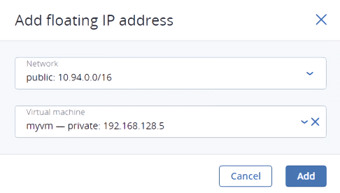
Click Add.
A floating IP address can be re-assigned to another virtual machine. Do the following:
- Click the ellipsis icon next to the floating IP address, and then click Unassign.
- Once the VM name disappears in the Assigned to column, click the ellipsis icon again, and then select Assign.
- In the Assign floating IP address window, select a VM network interface with a fixed private IP address.
- Click Assign.
To remove a floating IP address, unassign it from a VM, as described above, then click the ellipsis icon again and select Delete.
5.8.6. Managing load balancers
Acronis Cyber Infrastructure offers load balancing as a service for the compute infrastructure. Load balancing ensures fault tolerance and improves performance of web applications by distributing incoming network traffic across virtual machines from a balancing pool. A load balancer receives and then routes incoming requests to a suitable VM based on a configured balancing algorithm and VM health.
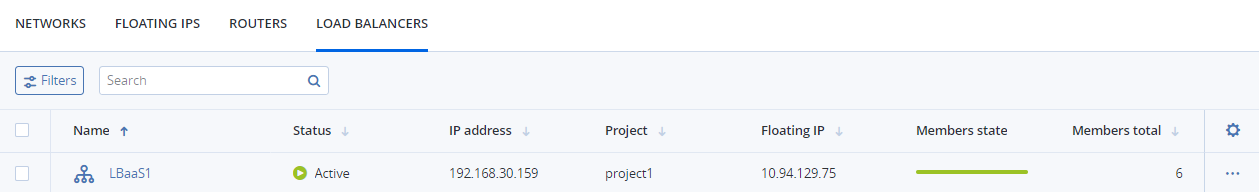
Load balancers can be created and edited by self-service users. Administrators can only monitor, disable/enable, and delete load balancers. In the admin panel, load balancers are shown on the Compute > Network > Load balancers tab.
Note
For self-service users to be able to create highly available load balancers, the compute cluster must have at least two nodes.
To monitor a load balancer’s performance and health, select it and open the Overview tab.
The following charts are available:
- Members state
- The total number of members in the balancing pools grouped by status: “Healthy,” “Unhealthy,” “Error,” and “Disabled”.
- CPU/RAM
- CPU and RAM usage by the load balancer.
- Network
- Incoming and outgoing network traffic.
- Active connections
- The number of active connections.
- Error requests
- The number of error requests.
By default, a load balancer instance is created with 2 vCPUs and 1 GB of memory. Check the CPU/RAM chart to see how the load balancer handles its workload. If the chart shows high values (about 80 percent), the load balancer needs more resources. You can add resources by changing the load balancer flavor, as described in Changing the default load balancer flavor.
You can see the load balancer parameters on its Properties tab.
In the Virtual machines field, you can see the name of load balancer instances. Click it to open the VM right pane.
To disable/enable or remove a load balancer, click the ellipsis icon next to it, and then click the desired action. To remove multiple load balancers at once, select them, and then click Delete.
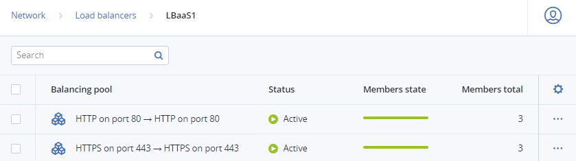
5.8.6.1. Managing balancing pools
To see a list of balancing pools in a load balancer, click its name.
You can open the pool right pane to monitor its performance and health on the Overview tab, see its parameters on the Properties tab, and manage its members on the Members tab.
To remove a balancing pool, click the ellipsis icon next to it, and then click Delete. To remove multiple balancing pools at once, select them, and then click Delete.