2.2. Configuring Node Network Interfaces
After configuring the networks, you need to assign them to the network interfaces on each node. A network can only be assigned to one network interface per node.
To assign a network to a network interface, do the following:
On the Infrastructure > Nodes screen, click a node to configure.
On the node overview screen, click NETWORK.
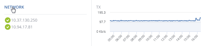
Select a network interface and click Configure.
On the Configure screen, do one of the following:
- To obtain the IP address, DNS, and routing settings from the DHCP server, select Automatically (DHCP).
- To obtain just the IP address from the DHCP server, select Automatically (DHCP address only).
- To specify the IP address manually, select Manually and add the IP address.
Warning
Dynamic IP address allocation will cause network issues as soon as the IP addresses of cluster nodes will change. Configure static IP addresses from the start or as soon as possible.
Note
For information about configuring RDMA-enabled network interfaces, see Enabling RDMA.
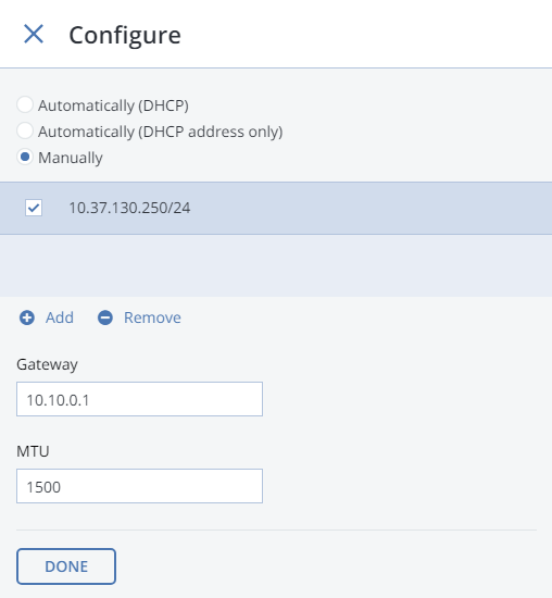
If necessary, set up a gateway and a DNS server. The provided gateway will become node’s default.
If you have set a custom maximum transmission unit (MTU) on the network hardware, set the same value in the corresponding field. See Step 2: Configuring the Network for more details.
Warning
Setting a custom MTU in admin panel prior to configuring it on the network hardware will result in network failure on the node and require manual resetting. Setting an MTU that differs from the one configured on the network hardware may result in network outage or poor performance.
Click Done to return to the list of network interfaces, do not change the selection, and click Assign network.
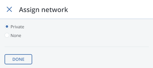
On the Assign network panel, select a network to connect the network interface to (for details, see Managing Networks and Traffic Types) and click Done.
2.2.1. Setting Up Network Bonding
Bonding multiple network interfaces is optional but provides the following benefits:
- High network availability. If one of the interfaces fails, the traffic will be automatically routed through the working interface(s).
- Higher network performance. For example, two bonded Gigabit interfaces will deliver the throughput of about 1.7 Gbit/s or up to 200 MB/s. For a storage node, the required number of network interfaces to bond may depend on the number of disks. For example, an HDD can deliver data at speeds of up to 1 Gbps.
To create a bond, do the following:
On the Infrastructure > Nodes screen, click the node to bond the network interfaces on.
On the node overview screen, click NETWORK.
In the NETWORK list, check network interfaces to bond, and click Create bonding in the menu to the right.
On the Configure Bonding panel, select the bonding type from the drop-down list. The
balance-xortype is selected by default and recommended for both fault tolerance and good performance.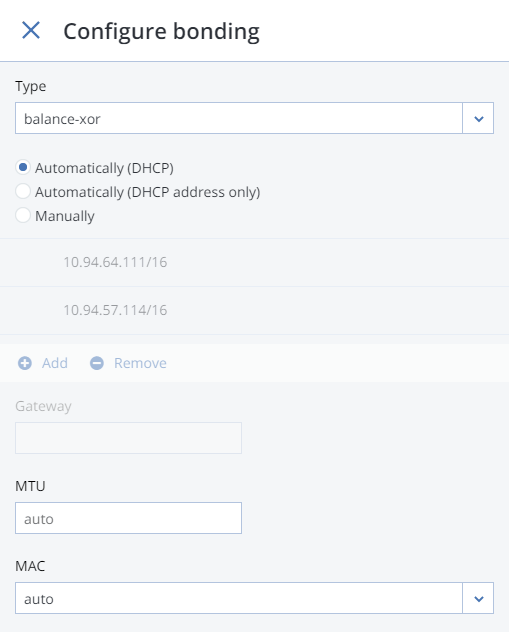
If you are bonding an Open vSwitch-based bridge used in the compute cluster with another network interface, two bonding types will be available:
balance-tcpandactive-backup. In thebalance-tcpmode, load balancing is done based on L2-L4 data like the destination MAC address, IP address, and TCP port. This mode requires that Link Aggregation Control Protocol (LACP) be enabled on the physical switch the node is connected to. In theactive-backupmode, one network interface is active and all other interfaces are passive. If the active interface fails, a passive one becomes active instead.Set up network parameters as described in step 4 in Configuring Node Network Interfaces and click PROCEED.
On the Assign network panel, select a network to connect the bonding network interface to (for details, see Managing Networks and Traffic Types) and click Done.
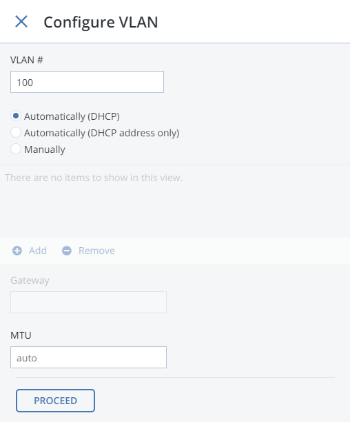
2.2.2. Creating VLAN Interfaces
To create a VLAN interface on a node, do the following:
On the Infrastructure > Nodes screen, click the node on which to configure VLAN.
On the node overview screen, click NETWORK.
Select a network interface and click Create VLAN.
On the Configure VLAN panel, specify a number for VLAN, add an IP address, and, if necessary, set up a gateway and a DNS server. The provided gateway will become node’s default.
On the Assign network panel, select a network to connect the VLAN network interface to (for details, see Managing Networks and Traffic Types) and click Done.