2.5. Planning Network
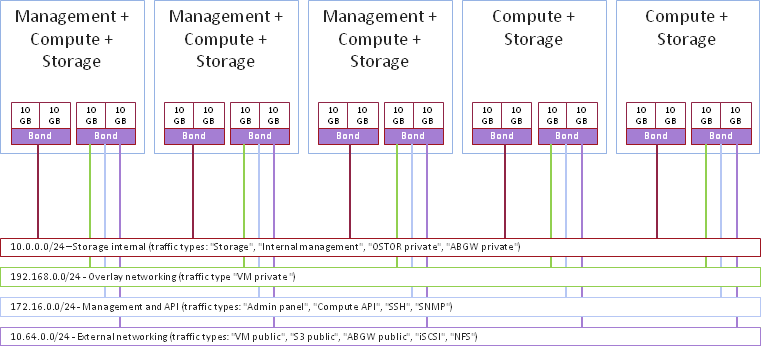
The recommended network configuration for Acronis Cyber Infrastructure is as follows:
- One bonded connection for internal storage traffic;
- One bonded connection for service traffic divided into these VLANs:
- Overlay networking (VM private networks)
- Management and API (admin panel, SSH, SNMP, compute API)
- External networking (VM public networks, public export of iSCSI, NFS, S3, and ABGW data)
2.5.1. General Network Requirements
- Internal storage traffic must be separated from other traffic types.
2.5.2. Network Limitations
- Nodes are added to clusters by their IP addresses, not FQDNs. Changing the IP address of a node in the cluster will remove that node from the cluster. If you plan to use DHCP in a cluster, make sure that IP addresses are bound to the MAC addresses of nodes’ network interfaces.
- Each node must have Internet access so updates can be installed.
- The MTU value is set to 1500 by default. See Step 2: Configuring the Network for information on setting an optimal MTU value.
- Network time synchronization (NTP) is required for correct statistics. It is enabled by default using the
chronydservice. If you want to usentpdateorntpd, stop and disablechronydfirst. - The Internal management traffic type is assigned automatically during installation and cannot be changed in the admin panel later.
- Even though the management node can be accessed from a web browser by the hostname, you still need to specify its IP address, not the hostname, during installation.
2.5.3. Per-Node Network Requirements
Network requirements for each cluster node depend on the services that will run on this node:
Each node in the cluster must have access to the internal network and have the port 8888 open to listen for incoming connections from the internal network.
All network interfaces on a node must be connected to different subnets. A network interface can be a VLAN-tagged logical interface, an untagged bond, or an Ethernet link.
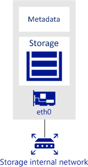
Each storage and metadata node must have at least one network interface for the internal network traffic. The IP addresses assigned to this interface must be either static or, if DHCP is used, mapped to the adapter’s MAC address. The figure below shows a sample network configuration for a storage and metadata node.
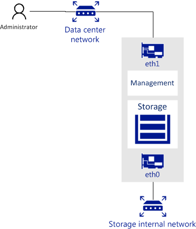
The management node must have a network interface for internal network traffic and a network interface for the public network traffic (e.g., to the datacenter or a public network) so the admin panel can be accessed via a web browser.
The management node must have the port 8888 open by default. This will allow access to the admin panel from the public network as well as access to the cluster node from the internal network.
The figure below shows a sample network configuration for a storage and management node.
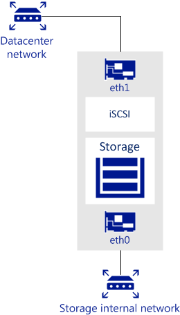
A node that runs one or more storage access point services must have a network interface for the internal network traffic and a network interface for the public network traffic.
The figure below shows a sample network configuration for a node with an iSCSI access point. iSCSI access points use the TCP port 3260 for incoming connections from the public network.
The next figure shows a sample network configuration for a node with an S3 storage access point. S3 access points use ports 443 (HTTPS) and 80 (HTTP) to listen for incoming connections from the public network.
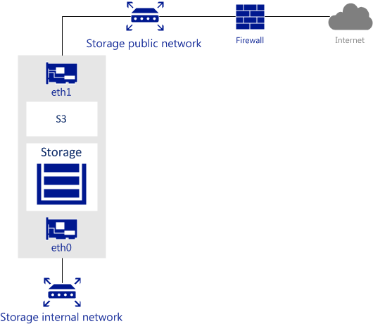
In the scenario pictured above, the internal network is used for both the storage and S3 cluster traffic.
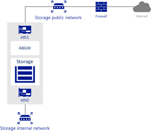
The next figure shows a sample network configuration for a node with a Backup Gateway storage access point. Backup Gateway access points use port 44445 for incoming connections from both internal and public networks and ports 443 and 8443 for outgoing connections to the public network.
A node that runs compute services must have a network interface for the internal network traffic and a network interface for the public network traffic.
2.5.4. Network Recommendations for Clients
The following table lists the maximum network performance a client can get with the specified network interface. The recommendation for clients is to use 10Gbps network hardware between any two cluster nodes and minimize network latencies, especially if SSD disks are used.
| Storage network interface | Node max. I/O | VM max. I/O (replication) | VM max. I/O (erasure coding) |
|---|---|---|---|
| 1 Gbps | 100 MB/s | 100 MB/s | 70 MB/s |
| 2 x 1 Gbps | ~175 MB/s | 100 MB/s | ~130 MB/s |
| 3 x 1 Gbps | ~250 MB/s | 100 MB/s | ~180 MB/s |
| 10 Gbps | 1 GB/s | 1 GB/s | 700 MB/s |
| 2 x 10 Gbps | 1.75 GB/s | 1 GB/s | 1.3 GB/s |
